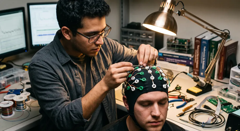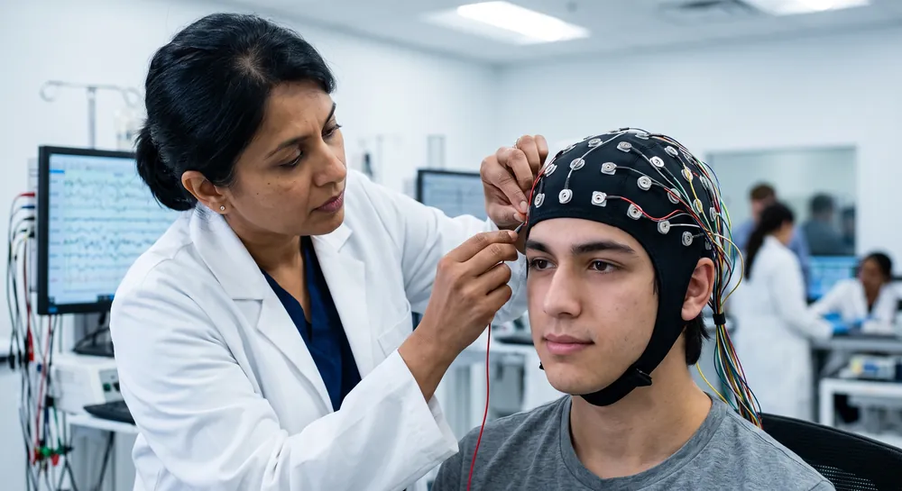
The location of a scalp electrode determines which populations of neurons contribute to the signal, shaping everything from clinical diagnosis to cognitive research. A millimeter’s shift can alter which brain region appears active.
For a technology that translates brain electrical activity into actionable insight, the physical placement of sensors is the foundational geometry upon which all interpretation rests. This article examines the anatomical reasoning behind the international 10-20 system, the critical assumption that makes it work, the challenges of special populations, and how modern verification tools reinforce the precision that reliable electroencephalogram (EEG) data demands.
What is EEG Electrode Placement?
EEG electrode placement is the process of positioning sensors on the scalp to record voltage differences associated with brain activity. Consistent placement helps clinicians and researchers compare recordings across time, participants, and settings. It is one part of electroencephalography, a method used in clinical care and neuroscience.
An electrode does not read activity from one isolated spot in the brain. Recorded signals reflect electrical sources and the way they spread through brain tissue, skull, and scalp, as well as the chosen reference and montage. For that reason, placement is interpreted alongside the full recording setup and the person’s clinical or research context.
The phrase standardized scalp locations describes the goal of a placement system, not a guarantee that every electrode sits over an identical cortical area in every person. Head shape, hair, and measurement technique can all affect the final position.
An EEG recording therefore depends on both the placement plan and the quality of its execution.
How the 10-20 System Creates a Universal EEG Map
Standardized placement turns the curved surface of a human head into a reproducible grid. The international 10-20 system achieves this by dividing the skull into proportional distances between four key craniometric landmarks: the nasion (the bridge of the nose), the inion (the bump at the back of the head), and the left and right pre-auricular points (just in front of the ears).
The name “10-20” comes from the intervals used (10%, 20%, 20%, 20%, 20%, and 10%) along the midline and coronal planes. These percentages define the locations of the familiar electrode labels: Fp (frontopolar), F (frontal), C (central), P (parietal), O (occipital), and T (temporal), each with numbered subdivisions that indicate laterality and distance from the midline.
A review by Richard Homan states that this method “employs measurements of external cranial landmarks to locate the electrodes on the scalp” and has served as the international standard for over three decades.
Its power lies in scalability. A technician in Tokyo and a researcher in Berlin can both place a Cz electrode at the vertex, defined as the intersection of the midline and the coronal line connecting the pre-auricular points. The resulting recordings reference the same anatomical location, enabling cross-laboratory comparison.
The updated American Clinical Neurophysiology Society Guideline extends this logic into the 10-10 system, which incorporates intermediate positions like AF1/2 and PO1/2. These extra sites offer greater spatial resolution, particularly useful when localizing epileptiform discharges or mapping subtle cognitive processes to specific cortical regions.
Without such a standardized EEG electrodes placement convention, the field would fragment into isolated datasets, each tethered to a lab-specific montage.
The Critical Assumption Linking Scalp to Brain Anatomy
Every EEG recording using the 10-20 system rests on the foundational premise that the relationship between an electrode’s scalp position and the underlying cerebral structure is consistent enough to be clinically and scientifically useful.
Richard Hamon’s review states this directly, noting that the technique “assumes a consistent correlation between scalp electrode locations and underlying cerebral structures.” Thus, this is the conceptual pillar that allows a neurologist to infer that activity recorded at T3 likely originates in the left temporal lobe, or that a Cz electrode captures activity from the sensorimotor cortices.
However, this assumption is just that—an assumption, not a verified anatomical law that applies identically to every brain.
Individual skull thickness, cortical folding patterns, and the exact relationship between the inion and the occipital pole can vary. The 10-20 system operates as a statistical model of head-brain correspondence, validated over decades of clinical correlation and source localization studies, but it does not provide a millimeter-precise map of any single person’s cortex.
When neurofeedback practitioners or researchers interpret EEG data without individual MRI co-registration, they are working within this probabilistic framework. The system’s widespread acceptance demonstrates that the assumption is robust enough for most applications, but epistemic humility requires acknowledging its limits. The data from a given electrode represent a weighted sum of activity from cortical patches, influenced by volume conduction, and the exact contributor mix is influenced by the individual’s anatomical idiosyncrasies.
This is why the proportional measurement method matters so much. By tying electrode positions to external landmarks that roughly scale with brain size, the system minimizes inter-individual variability. The alternative—placing electrodes at absolute distances from some arbitrary point—would collapse under the substantial variation in head circumference across adults and across ages.
Why Standardized Electrode Names Prevent Data Misinterpretation
The names assigned to each site must convey precise anatomical information to any trained reader. The nomenclature of the 10-20 system encodes both the lobe and the hemisphere: odd-numbered suffixes denote the left side, even-numbered the right, and “z” (zero) indicates the midline. An electrode labeled P3 is universally understood to sit over the left parietal region, approximately 20% of the half-circumference from the midline.
The updated American Clinical Neurophyisiology Society guideline, addresses why this standardization matters for communication. It discusses situations where the extended 10-10 system provides “additional localizing information,” such as using AF1/2 and PO1/2 positions to better define frontal pole or occipital pole activity. A report that simply mentions “frontal activity” without these standard labels could refer to a dozen different montage configurations. The guideline exists to prevent such ambiguity.
The same principle applies to consumer EEG headsets. A device with fixed electrode positions implicitly adopts a simplified subset of the 10-20 locations, and the quality of the research or application depends heavily on how faithfully those positions correspond to the intended cortical targets. Thus, consistent nomenclature allows data from a commercial headset to be compared against the vast clinical literature, provided the montage is transparently reported.
Marker | Meaning | Example |
|---|---|---|
Odd numbers | Left hemisphere | P3 |
Even numbers | Right hemisphere | P4 |
z | Midline | Cz |
Adapting Electrode Placement for Infant Brain Anatomy
Infant skull proportions, open fontanelles, and the trajectory of brain development alter the relationship between external marks and functional regions. A study by Hellström et al. addresses this directly, examining electrode placement in infants “studied radiographically" using plain skull X-ray films from 28 infants.
The researchers proposed a system with fewer electrodes than the full 10-20, tailored to infant anatomy. The radiological analysis allowed them to estimate the topographic relationship between each electrode position and the underlying brain parts, providing an anatomical validation specific to this age group.
The key takeaway is that the principle of proportionality remains, but the landmarks and the number of electrodes must be adjusted. For a portable EEG application intended for neonates, a vendor cannot simply place sensors at scaled-down adult coordinates. Without independent validation, the signals might misrepresent the underlying neural sources.
Using Outside-Hairline Placements for Sleep Monitoring
Clinical sleep studies present a practical challenge: the standard 10-20 montage requires scalp contact that can be intrusive for sleeping subjects, especially in longitudinal or at-home protocols.
Dyson et al. investigated whether EEG electrodes placed outside the hairline could yield sleep staging results comparable to standard placements. Six subjects slept with simultaneous recordings from standard positions and “test” placements outside the h airline, where adhesive pregelled electrodes could be more easily applied.
The agreement between sleep scores derived from the two placements was quantified using Cohen’s kapPa. The within-observer agreement between placements reached kappa \= 0.860 for the six sleep stages considered separately. This excellent agreement indicates that, for the purposes of staging sleep, outside-hairline placements can perform nearly as well as the standard montage.
Noteworthy, the finding is application-specific. It does not imply that outside-hairline electrodes can replace standard placements for detecting focal interictal spikes or for source localization. The study speaks to the flexibility of EEG methodology when the research question is narrow.
A consumer EEG cap designed for sleep tracking might therefore opt for a simplified array around the forehead and mastoids, but a researcher interpreting that data must know that spatial resolution is compromised.
Automated 3D Scanning Verifies Electrode Positions
Even with the 10-20 guidelines manual measurement introduces human error. A slight misjudgment of the nasion-to-inion distance, or a tape measure that slips, can shift an electrode by centimeters, mislabeling which brain region is being sampled.
As a consequence, Tveter et al. presented a novel automated method that uses 3D scans to localize electrode positions without requiring MRI data. The framework identifies pre-auricular points and other landmarks, then localizes each electrode, achieving correct electrode identification in the range of 85.7% to 91.0% on a dataset of over 400 scans from 278 subjects.
Notably, this method worked even when the MRI wasn’t unavailable, which is the reality in many resource-limited settings and in the growing field of ambulatory or home-based EEG. The end-to-end framework includes a validation tool for manual adjustments if necessary. The high accuracy suggests that automated spatial verification can become a standard quality-control step, much like impedance checks.
This study validates the localization technology itself and supports a logical inference: if an electrode is more certainly placed where it is supposed to be, the source localization will be more trustworthy. The convergence of affordable 3D scanning and open-source processing pipelines means that rigorous placement verification is no longer confined to well-equipped academic centers.
In any EEG study using an EEG machine with a defined montage, the ability to objectively confirm electrode positions raises the standard of evidence.
Preparing for EEG Electrode Placement
Preparation supports consistent contact and reduces avoidable interruptions during recording. The process varies with the electrode type, the duration of the study, and local clinical or research procedures. It generally involves confirming the planned layout, preparing the scalp as appropriate, and checking that the recording system is ready.
A simple sequence helps keep the setup organized without treating every participant or device as identical:
Confirm the intended electrode layout and montage against the recording protocol.
Identify and measure the relevant anatomical landmarks before positioning electrodes.
Prepare scalp contact areas according to the electrode design and established procedure.
Check electrode connections and signal quality before the recording proceeds.
After these steps, staff can assess whether each sensor is seated as intended and whether the observed signal is stable enough for the protocol. Electrode contact measures and acceptable thresholds depend on the equipment and institutional procedure, so a single value is not universal. Clear notes about placement or setup adjustments can help explain differences in the resulting data.
Troubleshooting Common Electrode Placement Issues
Placement problems may appear as poor contact, unstable traces, excessive noise, or unexpected differences between channels. These signs can arise from several sources, including loose connections, movement, hair interference, or environmental artifacts. Troubleshooting works best when the recording is considered as a system rather than attributing every irregularity to one electrode.
A first review checks whether the electrode is at the planned location and makes reliable scalp contact. The technician may also inspect cables, connectors, and the electrode-skin interface, following the equipment’s instructions. Any adjustment should preserve the intended layout or be documented if a change is necessary.
Some irregular activity is physiological rather than technical. Eye movements, muscle activity, and motion can affect scalp recordings, while reference choices can alter the appearance of channels. Separating these possibilities requires attention to the recording context and the pattern across channels; a single unusual trace does not by itself establish a cause.
Putting 10-20 Placement into Practice with Emotiv Flex 2 and EmotivPRO
The principles above shape real equipment choices. A fixed-layout headset commits you to one montage, while a cap-based system lets you match the electrode layout to your research question.
The Emotiv Flex 2 is a wireless, cap-based EEG system built around that flexibility. Its cap has 74 openings aligned with standard 10-20 positions, and you can place up to 32 sensors in any of them. The two reference sensors (CMS/DRL) can sit at any 10-20 location or on the ears. That makes it practical to build the frontal, central, or occipital layouts a protocol calls for, and to report them using standard electrode names.
Flex 2 is available with gel or saline sensors, and the cap comes in multiple sizes to fit different head dimensions. It streams 16-bit data at 256 samples per second per channel over Bluetooth 5.2.
Cap sizing helps with fit, but it does not replace measuring from the nasion, inion, and pre-auricular points. A well-fitted cap still needs its Cz checked against those landmarks.
EmotivPRO supports the setup and quality-control steps described earlier:
Real-time contact quality map: see each sensor's status as you set up, then adjust before recording starts.
EEG quality metrics: an additional per-sensor indicator based on signal characteristics, not contact alone.
Event markers: annotate the recording to separate experimental events from artifacts like blinks and movement.
Open export formats: export to EDF or CSV for analysis in tools like EEGLAB and MATLAB, with Lab Streaming Layer support for synchronized workflows.
Together, these features address several common placement challenges. Moving up to 32 sensors across 74 standard openings lets you match the montage to the research question. Multiple cap sizes support a snug, consistent fit across different head sizes. The contact quality map confirms sensor contact in real time, and standard electrode labels carry through into exported data, which supports transparent reporting of the montage.
Why Electrode Placement Sets the Limits of EEG Accuracy
Every EEG record inherits its meaning from where sensors rest, and the clarity of that signal depends on the geometry linking the scalp to the brain. Standardized proportional grids like the 10-20 system make recordings comparable across clinics, but their reliability rests on a probabilistic assumption rather than an exact anatomical map.
That assumption is strong enough for everyday use yet approximate enough to demand humility when interpreting signals from any individual head. This core idea explains why infant placements require separate validation, why simplified sleep arrays can be acceptable only for narrow questions, and why objective verification matters.
What unites all these findings is a single principle: the value of any EEG observation depends on knowing where it came from. Simplified montages may be practical for sleep staging, and automated 3D scanning may confirm sensor locations with high accuracy, but neither replaces anatomical reasoning.
Taken together, these studies show that precise sensor placement is not an optional preprocessing step but the foundation that lets a recording be shared, compared, and trusted. Even as EEG hardware becomes more portable and automated, the first question should remain the same: which part of the brain is under this electrode?
References
Homan, R. W. (1988). The 10-20 electrode system and cerebral location. American Journal of EEG Technology, 28(4), 269-279. https\://doi.org/10.1080/00029238.1988.11080272
Acharya, J. N., Hani, A. J., Cheek, J., Thirumala, P., & Tsuchida, T. N. (2016). American clinical neurophysiology society guideline 2: guidelines for standard electrode position nomenclature. The Neurodiagnostic Journal, 56(4), 245-252. https\://doi.org/10.1080/21646821.2016.1245558
Hellstrom, B., Karlsson, B., & Müssbichler, H. (1964). Electrode placement in EEG of infants and its anatomical relationship studied radiographically. American Journal of EEG Technology, 4(4), 71-75.
Dyson, R. J., Thornton, C., & Dore, C. J. (1984). EEG electrode positions outside the hairline to monitor sleep in man. Sleep, 7(2), 180-188. https\://doi.org/10.1093/sleep/7.2.180
Tveter, M., Tveitstøl, T., Nygaard, T., Pérez T, A. S., Kulashekhar, S., Bruña, R., ... & Hebold Haraldsen, I. R. (2024). EEG electrodes and where to find them: automated localization from 3D scans. Journal of Neural Engineering, 21(5), 056022.
Frequently Asked Questions
What is the 10-20 system and why is it used?
The 10-20 system is an international standard that places EEG electrodes on the scalp using proportional distances between key bony landmarks like the nasion and inion. It creates a reproducible grid so recordings from different labs and clinics refer to the same anatomical locations.
Why does a small shift in electrode placement matter?
A millimeter's shift can change which populations of neurons contribute to the signal, altering which brain region appears active. Precise placement ensures that data from an electrode actually represents the intended cortical area.
What critical assumption does the 10-20 system rely on?
The system assumes a consistent correlation between scalp electrode locations and underlying cerebral structures. This assumption is a statistical model, not an exact anatomical law, because individual skull thickness and cortical folding vary.
How do electrode names in the 10-20 system indicate location?
Each name encodes the lobe and hemisphere: odd numbers are left, even numbers right, and "z" means midline. For example, P3 is over the left parietal region, allowing any trained reader to understand the exact location.
Can standard electrode placements be used directly on infants?
No, infant skull proportions and brain development differ, so the adult 10-20 system cannot be simply scaled down. Researchers have validated tailored systems with fewer electrodes using radiological imaging to match positions to infant brain structures.
Are outside-hairline electrodes suitable for sleep monitoring?
For staging sleep, outside-hairline placements agree nearly as well with standard placements, making them practical for at-home or longitudinal sleep studies. However, they do not provide enough spatial resolution for detecting focal spikes or precise source localization.
How does automated 3D scanning improve electrode placement?
The method uses 3D scans of the head to identify landmarks and localize electrode positions without requiring MRI. This provides objective verification of where electrodes actually sit, reducing human measurement errors and improving trust in source localization.
Is the 10-10 system a replacement for the 10-20 system?
The 10-10 system is an extension, not a replacement, built from the same proportional logic and landmarks. It adds intermediate electrode positions like AF1/2 and PO1/2 for greater spatial resolution when needed.
Emotiv is a neurotechnology leader helping advance neuroscience research through accessible EEG and brain data tools.
Medical Disclaimer: The information provided on this website is for educational and informational purposes only and is not intended as medical or health advice. This content may contain errors and should not be relied upon to make life-altering health, medical, or lifestyle choices. Always seek the advice of your physician or other qualified health provider with any questions you may have regarding a medical condition or treatment.
Christian Burgos