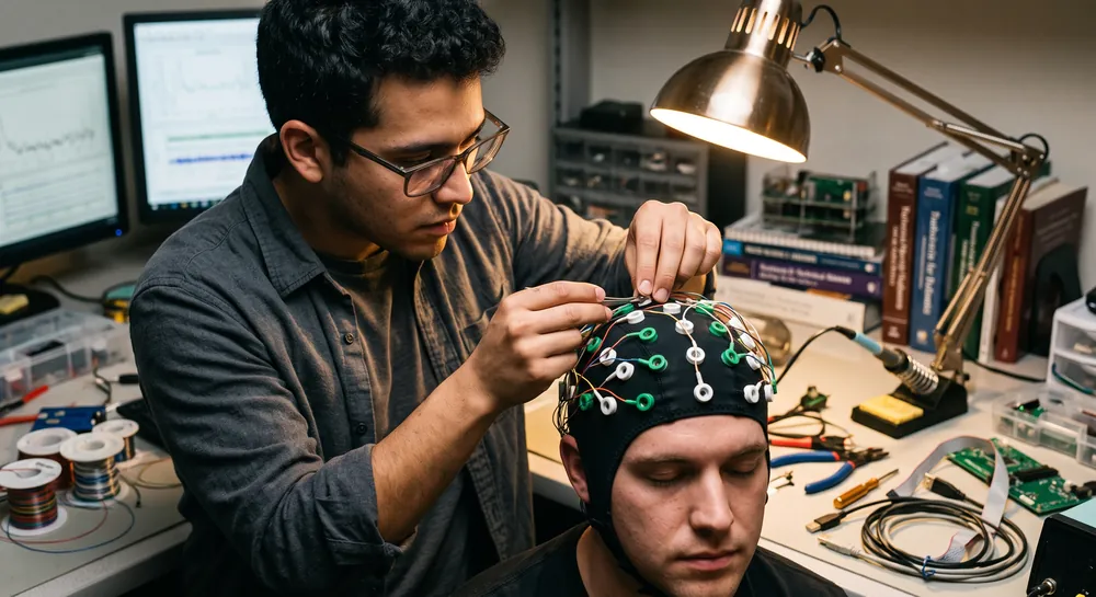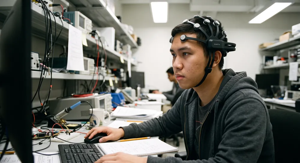
EEG electrodes provide the electrical interface between the scalp and an electroencephalography recording system. Their material, design, placement, and contact method all influence signal quality and practical use.
What are EEG Electrodes?
EEG electrodes are conductive sensors used to record electrical potential differences from the scalp. They do not generate brain activity or directly observe individual neurons; instead, they detect voltage changes that reach the scalp through the tissues of the head. The resulting signals are sent to an amplifier and recording system for visualization and analysis.
How Electrodes for EEG Work to Capture Brain Signals
At the skin–electrode interface, ionic activity in the body is converted into an electrical signal that the recording system can measure. The amplifier compares signals from different electrodes, often against a reference or through a defined montage, to produce voltage traces over time. Because the signals are small, stable contact and careful control of interference are central to usable recordings.
The electrode itself is only one part of the measurement chain. Skin preparation, conductive media, cable movement, electrode impedance, environmental electrical noise, and physiological artifacts can all affect the recorded waveform. Consequently, EEG data must be interpreted in relation to the recording setup and the participant’s condition rather than treated as a direct, unfiltered picture of brain activity.
Types of EEG Electrodes
EEG electrodes are often grouped by the way they make and maintain electrical contact with the scalp. Wet designs use a conductive medium, dry designs operate without added gel or liquid, and semi-dry designs introduce a smaller or more controlled amount of fluid.
These categories describe the interface, not a simple ranking from best to worst. The appropriate design depends on the duration, setting, density, and purpose of the recording.
Wet EEG Electrodes
Wet EEG electrodes use gel, paste, saline, or another conductive medium between the electrode and the scalp. The medium can reduce the impedance at the skin interface and help maintain a stable connection during a recording. Conventional clinical and research systems frequently use this approach because it can support consistent signal acquisition when preparation is performed carefully.
The trade-off is preparation and cleanup. Hair may need to be moved aside, the scalp may require preparation, and each contact may need to be filled or refreshed with conductive material. Excessive movement, drying of the medium, or uneven application can still introduce artifacts. Wet electrodes therefore combine strong contact performance with a more involved setup process.
Dry EEG Electrodes
Dry EEG electrodes are designed to contact the scalp without a separately applied conductive gel or liquid. Their surfaces may use conductive metals, coatings, pins, or other contact geometries that accommodate hair and scalp contours. By removing much of the preparation and cleanup associated with wet systems, dry electrodes can be useful in portable, repeated, or time-sensitive recordings.
Their performance is sensitive to mechanical fit and contact pressure. Hair, skin texture, movement, and electrode geometry may affect impedance and comfort, particularly in high-density arrangements. Dry systems can simplify deployment, but simplified preparation does not eliminate the need to assess signal quality and artifacts.
Semi-Dry EEG Electrodes
Semi-dry EEG electrodes occupy an intermediate position between wet and dry designs. They use a limited supply of conductive fluid, often delivered through an integrated reservoir or controlled channel, rather than requiring the same amount of gel applied manually to every electrode. This arrangement seeks to preserve reliable contact while reducing preparation and cleanup.
The design introduces its own engineering considerations, including fluid management, reservoir capacity, leakage control, and long-session stability. Semi-dry electrodes can be useful when a recording needs more consistent contact than a fully dry interface but less preparation than a conventional wet setup. Their practical value depends on how well the system balances contact quality, comfort, and operating time.
Disposable EEG Electrodes for Single-Use Applications
Disposable EEG electrodes are designed for one recording session or another limited-use interval defined by the product instructions. They can reduce cross-patient contamination concerns and simplify logistics when cleaning and reprocessing reusable components would be impractical. Many disposable formats use an adhesive or conductive interface that is packaged for controlled application.
Single-use designs are particularly relevant when rapid setup, infection-control procedures, or consistent preparation is a priority. Their environmental and operational costs should also be considered, including packaging, waste handling, storage conditions, and the need for replacement stock. A disposable electrode is not automatically suitable for every duration or recording density; its intended use and contact behavior remain central.
Moreover, signal quality depends on skin contact, placement, cable security, and the condition of the adhesive or conductive layer. During interpretation, a disposable electrode should be treated as one component of the acquisition chain rather than as a guarantee of artifact-free data. Clear labeling of electrode type, placement, and session timing supports later review and comparison.
Materials Used in EEG Electrodes
The electrode material affects electrochemical behavior, durability, mechanical properties, and compatibility with the intended recording method. A material must support a stable interface with the conductive medium and the body while producing manageable noise and polarization characteristics. The electrode’s coating, shape, connector, and amplifier arrangement also matter, so material alone does not determine performance.
Silver/Silver Chloride (Ag/AgCl)
Silver/silver chloride, commonly written as Ag/AgCl, is widely used for biopotential recording. Its electrochemical characteristics can support a relatively stable interface when used with an appropriate chloride-containing conductive medium. Ag/AgCl electrodes are available in disposable and reusable formats and may be produced as discs, cups, sensors, or integrated contacts.
The chloride balance at the interface is relevant to stability. Reusable electrodes require appropriate cleaning and inspection, while disposable versions are designed around a single recording session or limited use specified by the manufacturer. In either case, consistent skin contact remains necessary for dependable data.
Gold
Gold is valued for its chemical stability and resistance to corrosion. Gold-coated or gold-alloy electrode surfaces may be selected when durability, cleanability, or long-term physical stability is important. The coating thickness, underlying material, surface finish, and contact design influence how the electrode behaves in practice.
Noteworthy, a gold electrode can still produce poor data if contact is inconsistent, cables move, or the surrounding environment introduces interference. Its advantages are therefore best considered as part of a complete electrode and recording-system design.
Active EEG Electrodes vs. Passive Electrode Materials
Passive electrodes transmit the measured potential through a lead to an amplifier located elsewhere in the system. Active EEG electrodes place a buffer or preamplifier close to the electrode, which can reduce the effect of cable motion and some forms of interference before the signal travels through the lead. This distinction concerns the electronics and signal path, not simply whether the electrode is made from silver, gold, or another conductive material.
The following comparison separates common considerations that are sometimes conflated when electrode systems are described:
Feature | Passive electrode | Active electrode | Practical implication |
|---|---|---|---|
Signal path | Signal travels through the lead before amplification | Initial buffering or amplification occurs near the contact | Active layouts can reduce sensitivity to some cable effects |
Material choice | May use Ag/AgCl, gold, or another conductive surface | Uses a conductive contact plus nearby electronics | Active status does not identify the electrode material |
Setup concerns | Contact quality and cable routing are central | Contact quality, power, electronics, and cable routing all matter | More components may require system-specific handling |
Typical design goal | Straightforward potential transmission | Preserve signal quality near the source | The benefit depends on the recording environment |
This distinction helps prevent an overly simple assumption that one material or electrode category is universally superior. The interface, electronics, reference scheme, and recording protocol work together to determine the quality of the final EEG signal.
Choosing the Right EEG Electrodes
Electrode selection begins with the recording objective. A short clinical examination, a high-density research protocol, a mobile study, and a long-duration monitoring session may place different demands on preparation time, comfort, stability, and spatial coverage. The recording environment also matters, especially when participants move or when other equipment is operating nearby.
A useful selection process weighs several practical variables rather than focusing on a single specification. These considerations commonly include:
Required signal stability and acceptable impedance over the session
Number of channels and the intended placement density
Preparation, cleanup, sterilization, and reuse requirements
Participant comfort, hair coverage, movement, and session duration
Compatibility with amplifiers, caps, connectors, and surrounding equipment
Standardized layouts can make placement more repeatable. The 10-20 placement system, for example, uses anatomical landmarks and proportional measurements to identify scalp positions. An EEG cap can further simplify repeated placement by holding multiple electrodes in a predefined arrangement, although the cap does not replace checking contact quality or documenting the montage.
The final choice is also shaped by data interpretation. Electrode location, reference selection, sampling settings, and artifact handling should be recorded alongside the signal so that results remain understandable and comparable.
Common Sites for EEG Electrodes on the Head
EEG electrodes are placed at standardized scalp sites identified by anatomical landmarks and proportional distances. Common labels include frontal, central, temporal, parietal, occipital, and midline positions. The letter-and-number naming system describes location relative to broad head regions and the left–right or midline arrangement.
The International 10-20 framework remains a foundation for many clinical and research montages. Denser systems extend the same logic with additional positions; the 10-10 electrode placement system adds intermediate locations for higher spatial sampling. The selected density should match the research or clinical question, because more electrodes increase setup and management demands as well as spatial coverage.
The 10‑20 System: Anatomical Anchors and Proportional Placement
The 10‑20 system is a proportional map calibrated to four bony landmarks that any technician can reliably palpate. The nasion (the bridge of the nose), the inion (the bump at the back of the skull), and the left and right pre‑auricular points (the indentations just in front of the ears) serve as the cardinal references.
A flexible tape is run along the median plane from nasion to inion, and along the coronal plane between the two pre‑auricular points. Electrode positions are then marked at 10% and 20% intervals of the total distances.
A position labeled C4, for example, is defined not by a fixed millimeter offset but by a fraction of the head’s circumference. This proportional logic automatically accommodates variations in head size and shape, making it possible to compare a child’s EEG with an adult’s or to pool data across continents.
Automated methods designed to locate electrodes from three‑dimensional scans prove just how tightly correct positioning depends on these landmarks. In a framework validated on more than 400 scans from 278 subjects, researchers developed a two‑tiered system that first identifies the pre‑auricular points and then registers electrode locations relative to those anchors.
The tool achieved correct electrode positioning accuracy in the range of 85.7% to 91.0%. This high degree of anatomical fidelity is essential for subsequent source localization, the computational process that estimates which brain regions gave rise to the scalp signals.
Without the proportional scaffold, the electrode’s coordinate would float in empty space, undermining any attempt to trace activity back to its cortical origins. The 10‑20 system thus converts a set of bony prominences into a reproducible coordinate system, and the fact that automated pipelines rely on those same landmarks confirms that the grid is not a theoretical convenience but a physical necessity.
Optimal Electrode Density: More Isn’t Always Better
A common intuition suggests that doubling the number of electrodes will double the spatial clarity of the recording. High‑density arrays with 64, 128, or even 256 channels are routinely seen as the most rigorous option. However, careful empirical testing on a large cohort offers a more nuanced picture.
One investigation examined how many channels are needed to track the neural encoding of running speech—a demanding auditory‑cognitive task—and found that performance did not simply climb with channel count. In a subject‑independent scenario where the same electrode layout was used for everyone, the decoding accuracy remained stable when the array was reduced from 64 channels down to 22. Even at the tighter criterion of allowing no more than a 10% drop in the quality metric, 32 well‑placed electrodes were adequate for 91% of the 90 participants.
The relationship became even more counterintuitive in the subject‑specific case, where electrodes could be selected per individual. Here, the highest correlation between the reconstructed brain signal and the actual stimulus was achieved with approximately 20 electrodes—not 64.
In fact, using the optimal subset of channels yielded correlations 29% higher than those obtained with the full, unpruned array. This improvement likely reflects the elimination of noisy or redundant channels that contribute more artifact than signal.
Noteworthy, the finding does not argue against high‑density recordings; it argues against the assumption that every added electrode adds value. The key is strategic channel selection anchored to a standardized layout.
The 10‑20 system provides the proportional scaffolding, but the research demonstrates that the effective density on that scaffold is not automatically maximal. For many applications, a moderate number of electrodes placed at the correct proportional coordinates delivers cleaner, more interpretable data than a dense helmet plugged into every available slot.
Electrode count | Finding |
|---|---|
64 channels | No extra accuracy gain |
32 channels | Sufficient for 91% |
~20 channels | 29% higher correlation |
Full array | Noisy, redundant channels |
How Montages and References Shape the Recorded Waveform
Every EEG channel represents the output of a differential amplifier, a circuit that subtracts the voltage at one input from the voltage at another. Anything that appears identically on both inputs—power‑line noise, sweat artifacts, or brain activity that is synchronous across the two recording sites—is cancelled.
The choice of which electrode serves as the reference (the “minus” input) therefore becomes an inextricable part of the measurement. Swapping the reference changes which brain rhythms survive the subtraction and which are silently discarded.
This principle has sparked a long‑standing discussion around referential versus bipolar EEG montages.
In a referential arrangement, each active electrode is compared against a common reference placed on a presumably neutral site, such as the earlobe or mastoid. A bipolar montage, by contrast, links each active electrode to a nearby neighbor.
A study by Fehmi & Collura explicitly notes that the differential amplifier “must destroy those elements of brain activity which are common (synchronous) to the recording electrodes.” Consequently, the physical distance between the two electrodes in a pair determines which spatial scales of cortical activity will be recorded.
A closely spaced bipolar pair will largely eliminate widespread, synchronous oscillations, whereas a referential derivation with a distant reference retains them. The manner in which the scalp’s bioelectrical field is sampled depends as much on the montage as on the individual electrode positions.
Furthermore, a controlled, multi‑center polysomnography trial illustrates how montage decisions translate into concrete clinical numbers. Scorers evaluated sleep records using either three referential EEG derivations recommended by the American Academy of Sleep Medicine (F4/M1, C4/M1, O2/M1) or a single central derivation (C4/M1) that followed older guidelines.
Therein, the authors found that switching to the three‑derivation montage caused a mean decrease of 9.6 minutes in stage N1 sleep and a mean increase of 10.6 minutes in deep N3 sleep. These are systematic shifts that could alter a clinical impression of sleep architecture, yet the same study found no significant change in inter‑scorer or intra‑scorer reliability. In other words, while the montage choice nudged sleep‑stage totals, it did not make the scoring process itself more erratic.
The lesson for anyone acquiring EEG data is straightforward: the reference and the montage are not post‑hoc accessories; they are part of the recording itself. A different EEG montage applied to the same raw scalp voltages can yield a different result, and standardization of these choices is what allows different laboratories to speak the same scientific language.
Verifying Placement: From Proportions to Physical Reality
Even when technicians meticulously measure the 10‑20 arc lengths, several factors can push an electrode away from its intended location. The cap can shift, hair can create uneven contact, and slight asymmetries in landmark palpation can propagate errors. Standardized positioning must therefore include a verification step and a way to check that the physical electrode really sits where the proportional grid says it should.
The aforementioned automated localization framework that demonstrated the primacy of the pre‑auricular points also addressed this verification problem directly. By capturing a 3D image of the head with electrodes in place, the algorithm registers each electrode’s coordinates and compares them against the expected 10‑20 positions. The method identifies the pre‑auricular points without requiring an MRI scan, making it feasible in resource‑limited clinical settings where radiological imaging is not routinely available alongside EEG.
The pipeline reported correct electrode positioning in the 85.7% to 91.0% range and includes a manual adjustment interface so that a technologist can visually confirm and nudge any misclassified electrode. Without such verification, a recording that is labeled “Cz” could in fact lie a centimeter anterior or lateral to the vertex, introducing a systematic offset that degrades source localization and reduces the comparability of the data with normative databases. Therefore, verification closes the loop between the idealized 10‑20 map and the physical reality of a cap on a living, moving head.
Placements Outside the Hairline: Trade‑offs and Evidence
The scalp’s hair‑covered regions present practical challenges. They require abrasive skin preparation and conductive gels that can be uncomfortable during long recordings, and they are especially inconvenient for ambulatory monitoring or for participants who must look presentable after a session. This has prompted interest in electrode placements outside the hairline, typically on the forehead and behind the ears, where simple adhesive electrodes can be applied quickly and comfortably.
A small but carefully conducted study examined whether such placements could substitute for standard scalp sites during sleep recording. Six healthy volunteers each slept for one night with both a standard electrode array and a test array outside the hairline.
Two independent scorers evaluated the records. The within‑observer agreement between the standard and test placements was encouraging when the six conventional sleep stages were kept separate: Cohen’s kappa reached 0.86, a value typically considered excellent.
Yet the same abstract reports a striking anomaly. When stages awake/1 and stages 3/4 were combined, the kappa between the two placement schemes dropped to 0.09, a value that would normally indicate near‑random agreement.
This discrepancy, reported without further explanation, raises caution. With only six subjects, the pattern might reflect an outlier or a specific vulnerability of combined‑stage scoring that the alternative placements cannot resolve.
The authors concluded that outside‑hairline electrodes “can be used effectively,” and for many applied studies the convenience trade‑off may be justifiable. For a student learning the fundamentals of reliable EEG acquisition, however, this evidence base remains thin. The small sample, absence of replication, and the peculiar kappa value mean that outside‑hairline placements do not yet offer a one‑to‑one replacement for standard scalp positions across all signal features.
The Foundation of Reliable EEG
Reliable EEG is built on a chain of controlled decisions. It starts with the proportional 10‑20 system that ties every electrode to the nasion, inion, and pre‑auricular points, ensuring that a measurement taken in one laboratory can be reproduced in another.
The research reviewed here then layers on three further insights:
First, that electrode density is not a linear good: 32 well‑chosen channels can suffice for 91% of individuals in a demanding speech‑tracking task, and in some cases fewer channels yield a cleaner signal than more.
Second, that the montage and reference are not neutral conduits; they subtract certain brain activities and preserve others, shifting sleep‑stage summaries by clinically meaningful margins even when scoring reliability remains intact.
Third, that placement must be verified with tools that map the physical electrode back to the intended anatomical coordinate, because even careful landmarking cannot entirely prevent drift.
The safest path for anyone entering the field is to master the standardized proportional framework, treat electrode density and montage as variables that demand justification, verify actual placements against the intended grid, and approach alternative recording sites with an awareness of their unsettled evidentiary status.
The Future of EEG Electrode Technology
Future development is likely to focus on making EEG acquisition more portable, repeatable, and comfortable without sacrificing signal quality. Smaller electronics, improved mechanical designs, flexible substrates, and better integration with head-worn systems may reduce setup burdens. These developments are relevant to clinical monitoring, research, neurofeedback, and brain–computer interface studies, although each application has different validation requirements.
Automation may also improve electrode placement and quality control. Systems can assist with identifying anatomical landmarks, checking contact status, recording channel maps, and flagging unstable signals during acquisition. Such tools can reduce avoidable technical variation, but they do not replace professional interpretation of EEG findings or the need to evaluate artifacts and protocol limitations.
Another direction is the integration of EEG headsets with other physiological or imaging measurements. Combined systems can provide complementary information, yet they also introduce synchronization, motion, electrical-safety, and data-management challenges. Progress will depend not only on new electrode materials, but also on transparent validation, standardized metadata, and careful separation between measured signals and clinical conclusions.
Why Reliable EEG Depends on More Than Just Good Equipment
High-spec amplifiers and advanced sensor materials are fundamental to modern electroencephalography, but high-end hardware alone cannot guarantee reliable EEG acquisition. Delivering actionable, high-fidelity brain data depends on the entire recording pipeline—from anatomical precision and strategic sensor configuration to rigorous verification.
Achieving reproducible results across clinical and research settings requires a holistic approach:
Standardized Positioning: Grounding electrode setup in the proportional 10-20 placement system ensures consistent mapping across diverse head shapes and enables precise source localization.
Strategic Sensor Density: Rather than maximizing channel count, selecting an optimal array (such as 22 to 32 targeted channels) often yields higher signal-to-noise ratios by eliminating redundant or artifact-prone channels.
Contextual Montage Selection: Choice of reference and montage (referential vs. bipolar) directly shapes recorded waveforms, determining which neural oscillations are preserved or subtracted.
Verification & Signal Quality: Using automated or 3D verification tools confirms that physical sensor placement aligns with anatomical targets, bridging the gap between ideal grids and real-world scalp application.
Ultimately, hardware quality is only as effective as the methodology behind it. By pairing appropriate electrode types—whether wet, dry, or semi-dry—with standardized protocols, researchers and clinicians establish the foundation for accurate, artifact-free EEG data interpretation.
References
Tveter, M., Tveitstøl, T., Nygaard, T., Pérez T, A. S., Kulashekhar, S., Bruña, R., ... & Hebold Haraldsen, I. R. (2024). EEG electrodes and where to find them: automated localization from 3D scans. Journal of Neural Engineering, 21(5), 056022.
Montoya-Martínez, J., Vanthornhout, J., Bertrand, A., & Francart, T. (2021). Effect of number and placement of EEG electrodes on measurement of neural tracking of speech. Plos one, 16(2), e0246769. https://doi.org/10.1371/journal.pone.0246769
Fehmi, L. G., & Collura, T. (2007). Effects of electrode placement upon EEG biofeedback training: The monopolar-bipolar controversy. Journal of Neurotherapy, 11(2), 45-63. https://doi.org/10.1300/J184v11n02_04
Ruehland, W. R., O'Donoghue, F. J., Pierce, R. J., Thornton, A. T., Singh, P., Copland, J. M., ... & Rochford, P. D. (2011). The 2007 AASM recommendations for EEG electrode placement in polysomnography: impact on sleep and cortical arousal scoring. Sleep, 34(1), 73-81. https://doi.org/10.1093/sleep/34.1.73
Dyson, R. J., Thornton, C., & Dore, C. J. (1984). EEG electrode positions outside the hairline to monitor sleep in man. Sleep, 7(2), 180-188. https://doi.org/10.1093/sleep/7.2.180
Frequently Asked Questions
What is the 10-20 system for EEG electrode placement?
The 10-20 system is a standardized method that uses proportional distances based on four bony landmarks: the nasion, inion, and pre-auricular points. Electrodes are placed at 10% and 20% intervals along the measured distances between these landmarks, automatically accommodating different head sizes and shapes. This creates a reproducible coordinate system that allows EEG data to be compared across sessions, laboratories, and individuals.
Does using more EEG electrodes always produce better data?
No, more electrodes do not automatically improve signal quality. Research shows that in some tasks, reducing from 64 to 22 channels does not decrease decoding accuracy, and in subject-specific cases, an optimal subset of about 20 electrodes outperforms the full array by eliminating noisy or redundant channels. Strategic channel selection on a standardized layout is more important than simply maximizing electrode count.
What is the difference between referential and bipolar EEG montages?
In a referential montage, each active electrode is compared against a common reference placed on a neutral site like the earlobe, preserving widespread synchronous brain activity. In a bipolar montage, each electrode is compared to a nearby neighbor, which cancels out activity that is common to both sites, effectively filtering out large-scale oscillations. The choice of montage determines which spatial scales of brain activity are recorded.
How does the choice of reference electrode affect the EEG signal?
The reference electrode serves as the subtraction input in a differential amplifier, so any activity that appears identically at both the active and reference sites is removed from the recorded signal. Swapping the reference can change which brain rhythms are preserved or discarded, meaning the recorded waveform is inherently shaped by the reference choice. This is why montage and reference are considered part of the recording itself, not post-hoc adjustments.
Why is it important to verify electrode placement after applying the cap?
Even with careful manual measurement, electrode caps can shift, hair can cause uneven contact, and landmark palpation errors can occur, pushing electrodes away from their intended positions. Verification using 3D imaging and automated algorithms can confirm that each electrode sits at the correct proportional coordinate, which is essential for accurate source localization and cross-session comparability. Without verification, a labeled electrode like "Cz" might actually be located elsewhere, introducing systematic errors.
Can EEG electrodes be placed outside the hairline without losing data quality?
Placements on the forehead and behind the ears offer convenience and comfort, but the evidence for their equivalence to standard scalp sites is limited. One small study found excellent agreement for separate sleep stages but near-random agreement when certain stages were combined, highlighting a potential vulnerability. The authors concluded they "can be used effectively," but due to the small sample and unreplicated results, they are best considered a compromise that must be evaluated for each specific application.
What are the key principles for obtaining reliable EEG signals?
Reliable EEG acquisition begins with the proportional 10-20 system to ensure consistent anatomical placement. Then, electrode density should be optimized strategically rather than maximized, and the montage/reference must be chosen deliberately because they shape which brain activity is recorded. Finally, physical electrode placement should be verified against the intended coordinates to prevent drift and maintain comparability.
How does the 10-20 system support source localization of brain activity?
The 10-20 system provides a reproducible coordinate framework anchored to bony landmarks, allowing each electrode's position to be expressed as a fraction of head dimensions. This proportional mapping ensures that the electrode coordinates are physically meaningful, which is essential for computational source localization that estimates which brain regions produced the scalp signals. Without this standardized scaffold, electrode positions would be arbitrary, and tracing activity back to cortical origins would be impossible.
Emotiv is a neurotechnology leader helping advance neuroscience research through accessible EEG and brain data tools.
Medical Disclaimer: The information provided on this website is for educational and informational purposes only and is not intended as medical or health advice. This content may contain errors and should not be relied upon to make life-altering health, medical, or lifestyle choices. Always seek the advice of your physician or other qualified health provider with any questions you may have regarding a medical condition or treatment.
Christian Burgos